
Building a Tesla coil feels almost like a rite of passage. Certainly my life didn’t feel entirely complete until I built one for myself. I’ve heard this project can be a little frustrating, and indeed it was. You should consider yourself fore-warned; if you undertake this project you are very likely to blow up quite a few transistors before you reach your goal. I did however, find a few tricks along the way which should help you save the lives of some innocent transistors, and perhaps reduce your frustration.
Step 1 — Winding a secondary
Winding the secondary isn’t too difficult, for a small coil you’ll need to find something something with a diameter of about 3 to 8cm. You’ll want to aim for around 1000 turns, but I suspect that a wide range of values should still work. My coil is around 700 turns, and winding by hand took me about 3 hours of time in front of the TV. The winding of my coil took me a lot longer than it should have because I used fairly crappy copper that I reclaimed from an old AC motor:

If you are winding your coil by hand I’d suggest you put a dab of super-glue or some other kind of sealant on the winding every inch or so to prevent your work from suddenly becoming undone. You’ll want to keep saving your progress.
This is what I ended up with after about 3 hours work. I enlisted the services of my 3d printer to make a little stand for the coil:

Step 2 — The Primary
There is quite a number of different ways to create a primary for a Tesla coil
See https://www.google.com.au/search?q=tesla+coil+primary&tbm=isch for quite a large range of configurations. Most of these primary configurations are geared toward solving issues that arise in high power Telsa coils. Higher power coils can develop issues whereby sparks run up and down the secondary coil or even jump from the secondary to the primary. Some Tesla coil designs also require fine-tuning the length of the primary, so using a bare-wire primary whose length can easily be adjusted with alligator clips is useful. For my small desktop Tesla coil using the slayer exciter circuit, none of this matters. The slayer circuit automatically tunes itself to the resonant frequency of the secondary, so fine-tuning of the primary isn’t required.
I did some experimentation with different kinds of coils. The primary which tended to work the best pleasingly was also the simplest. I just wrapped 3 or 4 loops of insulated wire around the secondary a small distance above the bottom of the coil and then used electrical tape to hold the primary in place.
Shown below is my very simple primary coil:

Step 3 — Top Load
The Tesla coil will still function without a top-load in place, but with a top load in place, the resonate frequency will be much lower. A lower switching frequency helps reduce the heat dissipated by your transistor, and in general, is less rough on your it. I’d recommend you don’t run your coil without a top-load as there is less chance of a blown transistor. Without a top-load my coil had a resonant frequency of about 2mhz. With a top-load added the frequency fell to about 1.5mhz; quite a significant reduction. The top-load for the coil can be any disc or spherical shaped object; I made my top-load out of a coffee-tin lid, for example.
Step 4 — Simple Slayer Exciter
This circuit is by far the simplest way to get your tesla coil up and running, you only need one transistor, and one LED:
This simplicity does come with a downside, as you increase the supply voltage your transistor will most likely die suddenly, and without any warning, this circuit can chew through transistors like nothing else. On the upside, with experimentation I found there are a few steps you can take to dramatically improve the lifespan of your transistors in this circuit.
The most important thing you can do, is exchange the LED for a Schottky diode. Shottky diodes can recover from reverse bias voltage much faster than regular diodes https://en.wikipedia.org/wiki/Diode#Reverse-recovery_effect. By using Schottky diodes, your transistor is exposed to the negative base/emitter voltages which are generated by the secondary coil for a much shorter length of time. It is also beneficial to use a larger transistor than the 22222 and also attach it to a big, big, BIG, heat-sink. The slayer exciter circuit causes a lot of heating in the transistor due to slow turn-on and turn-off times.
Improved Slayer Exciter:

In this improved circuit, we’ve replaced the LED with a much faster Schottky diode, D1. This diode does a much better job of preventing the collector-emitter junction from being pulled below ground. If the voltage on the base of Q1 is lowered below 0V (Say to -2V) then current will flow through D1 (which is at 0V) and return the base of Q1 to 0V. This drop in voltage at Q1 below ground can occur due to the inductance of the secondary coil.
D2 is added to protects Q1 from high voltages which may develop on the primary coil. The 1N5819 will break-down at about 40V which is comfortably below the TIP31Cs 100V rating.
C1 has been added to the circuit to stabilize the oscillations and to provide the impulses generated by the secondary somewhere to safely dissipate.
A lot of schottky diodes could be used here instead of the 1n5819. Any Schottky diode with a breakdown of between 20 and 80V would likely be a fine replacement. The rating doesn’t really matter and it’d be cheaper to stick to 1 amp ones
An important thing to keep in mind with this circuit is it will only operate if the current is passing through the primary in the right direction, if your circuit fails to oscillate, first try reversing the connections on the primary winding.
Here’s a shot of the slayer exciter in operation:
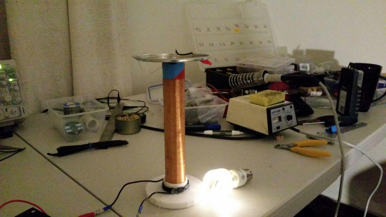
With the above modifications, you should be able to run the slayer-exciter circuit on much higher voltages without your transistors blowing up. This circuit is capable of lighting fluorescent from 3 to 6 inches away and even creating small (5mm?) sparks.
On the next post I build a much more powerful version of the slayer exciter circuit.
Here’s a sneak-peak of what the more powerful version can achieve:

Thnx bro it’s working but i can not get higher sparks “how can i make longer HV Sparks”
LikeLiked by 1 person
You can get longer sparks by winding a longer coil; or by moving onto this circuit
https://siliconjunction.wordpress.com/2017/02/25/my-first-tesla-coil-mosfet-version/
LikeLike
Hey, can I use a 100v 3300 microfarad capacitor? The others I have are 25v 100 microfarad!
Thanks a lot!
LikeLike
You sure can
LikeLike
Sorry for beeing pedantic, but it’s “rite of passage”, not “right of passage”, so “rite” like ritual or ceremony, not “right” like entitlement.
LikeLiked by 1 person
You are most certainly correct, thanks!
LikeLike
Thanks buddy for the heads up on the blown transistors. Had not thought of frequency overload. I am using MJL21194, as I have quite a few.
LikeLiked by 1 person
hey , thank you for the information about Schottky diode and capasitor i didnt know about that , so the capasitor her job is about helping the transistor to get the right frequency resonance and filter the voltage am i right ? and please do you have any idea how to calculate the current in the primary ? thank you !
LikeLike
[…] Download Image More @ siliconjunction.wordpress.com […]
LikeLike